
As I mentioned in my last post, the bobbin winder that I fabricobbled together for my 201K3, while it works with an attached belted motor, isn’t going to work with the servo motor setup that this machine is going to be using.
There are a couple of solutions:
- Use another machine to wind bobbins.
- Buy any one of a number of stand alone bobbin winders (prices range from a low of about $20 to over $60)
- Make my own.
I think you know where this is going…
One of the joys of having had a real shop in the garage for about 30 years is I have a great collection of “stuff”. Some who are less tolerant of clutter may call it “crap” or even something less family friendly, but to me, it’s a treasure trove of stuff, just waiting to get put back into service.
The same can also be said for the repair shop. From time to time, I am either given, or I find by the side of the road, machines that nobody wants, that have sewn their last stitch. Just because they are retired or not financially viable repair projects doesn’t mean they have zero value. Such was the case for a 1980’s Brother sewing machine that recently came my way. It was a 15 class zigzag that was way beyond repair, so I took it apart, saved all of the hardware and electrical components, as well as a few “Lego” sewing machine parts such as hook mechanism, presser, and needle bar parts. The rest of the carcase was cast away and is off to the recycle center.
I happened to have a bobbin winder mechanism designed for industrial machines. I keep that winder on hand in case a local tailor shop whose machines I service has yet another unit fail. They are inexpensive ($12.95 from Wawak), and are the perfect starting point for my project.

These units are intended to be installed on the sewing table at the balance wheel side of the machine. They are normally driven by the same belt that runs the sewing machine, but this wouldn’t work in my application as the geometry of the two machines that will share the table won’t allow the winder to be attached to the table and not have the other machine interfere. This is going to have to be a stand alone unit.
I’m kicking myself now for not taking pictures of the build process. Honestly, it went so fast, I didn’t even think about it. Starting with the winder unit, I went looking at my available stash of electric motors that could be pressed into service. My first instinct was to work out a belt drive arrangement, but that was a non-starter as to have done so would have negated the auto stop-on-full function of the winder. A friction drive was the order of the day.
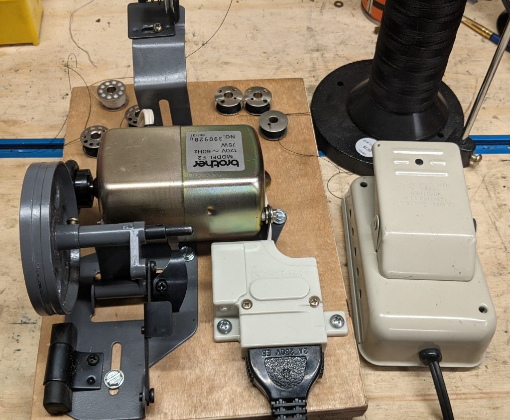
Friction drive is a great concept, but sewing machine motors (which is what I have a lot of) have small pulleys on their shafts, and I had nothing that even resembled a friction drive. Nothing, that is, until I pulled out the motor from that dead 1980’s Brother. It had a small pulley all right, but it also had something NONE of my other motors had, a large round hunk of plastic on the shaft! A round hunk of plastic just enough larger than the inside diameter of a standard bobbin tire, that adding a bobbin tire to the outside makes the perfect friction drive! It got even better right away, there was a bracket welded onto the frame that I would have to partially cut away, the remaining portion of which make an excellent mounting tab! There was even another mounting bracket bolted to the back of the motor. It was as if the designers at Brother 40 years ago anticipated my every need/want/desire right down the line. To add even greater bliss, the power block is fully enclosed and has two mounting tabs. The Gods of Sewing Machines smiled down upon me this day!
Off to the workshop!
I gathered up the motor, power block, foot controller, and winder assembly and headed off to the garage.
Pawing through my scrap bin, I found a nice piece of 3/4″ birch plywood about 7″ wide and 24 inches long. I started playing around with the position of the parts and realized that I was going to have to modify the base of the bobbin winder mechanism to make this work. In order to keep the footprint reasonably small, I was going to have to place the motor across the base of the winder assembly. This was going to put the motor right in the middle of the thread path, something that would NOT be conducive to good bobbin winding. My solution was to determine where the motor was going to be, then bend the base of the winder assembly 90 degrees up, then at a reasonable height to clear the motor, bend it 90 degrees again back to the horizontal.

I made the necessary bends, played with the placement once again, and decided that I would keep the 7 inch width of the plywood, but cut it at 10 inches long. One quick pass with the circular saw, a little sanding to clean up the edges, and I took my plywood outside with a spray can of Krylon Crystal Clear to put a protective clear coat on the bottom. Once that was sprayed, I installed screw on rubber feet in all four corners, turned it over and sprayed the top and sides with two coats of the clear.
The next step was to amputate the excess material from the motor bracket (air powered, 3″ cut off tool to the rescue), and drill a few mounting holes.
From here out, it was just screwing the components down to the plywood. It took just a few minutes. I spent more time looking for the perfect hardware than I did installing it!


There is, as always, an alignment procedure to make this type of winder wind a bobbin evenly. I plan on doing a quick demonstration video which will be eventually posted to my YouTube channel.
Conclusion
This was a fun, very quick, very inexpensive project that should give us years of good service. I believe I have described it well enough for anyone who wishes to duplicate the effort. Sourcing the motor may be problematic – I don’t recall the model number of the machine it came from, nor do I know if all Brother motors of the model F2 have the same mounting brackets or plastic part. Having said that, it shouldn’t be too tough to scratch build a friction drive.
Enjoy!